Any modern enterprise operates in complex scenarios in which it often relies on third enterprises for the provisioning of services or resources to create value for its customers. In turn, these « third » enterprises have interactions of various forms with other enterprises. Overall, these enterprises build the so-called Systems of Systems (SoS) configurations, i.e. physically distributed independently governed and managed systems [1]. Thus, enterprises establish chains of interdependencies that cross multiple lifecycle processes (operations, maintenance, governance) and that are therefore not always consistently and intuitively to visualize. For example, an airline company relies on multiple companies for the operational activities (e.g. refueling, catering, on-ground services, etc.), for maintenance activities (e.g. pilot training, airplane revisions and repairs, etc.), and for the governance activities.
Enterprise architecture (EA) frameworks have often been introduced to model enterprises within a defined scope of interest, focusing on the internal elements, the external elements at the boundary, and their relationships. Consequently, existing frameworks are not always suitable to model the complex interdependencies across the lifecycle processes in multi-enterprise scenarios. However, architectural frameworks already use a metaphor with the visual world for defining concepts to structure the enterprise model. Specifically, concepts such as Viewpoint and View can be effectively used to partition and render the model in a manageable manner to the human audience, reducing its complexity and focusing on the areas of concerns to groups of stakeholders.
The visual metaphor provides also further hint on a new concept that could allow EA frameworks to represent complex cross-lifecycle dependencies in multi-enterprise scenarios. In the human perception, one a third concept is available: the frequency of the electromagnetic radiation that gives origin to the phenomenon of colors. In this article, we build on this visual metaphor to show how a third concept “Viewband” can complement the existing architectural concepts of Viewpoint and View to represent the lifecycle interdependencies in a machine interpretable manner [2]. The new concept is in elegant harmony with the visual metaphor when having to mechanically show the interdependencies of a single lifecycle process, like seeing the world through a colored lens that filter in only the colors (frequency band) of interest.
Architectural Concepts
IEEE defines architecture as “the fundamental organization of a system embodied in its components, their relationships to each other, and to the environment, and the principles guiding its design and evolution” [3]. The standard also specifies that an architecture can be represented by one or more architectural descriptions, depending on specific rationales. In turn, an architectural description addresses the needs of an identified set of stakeholders and consists of Views and Viewpoints.
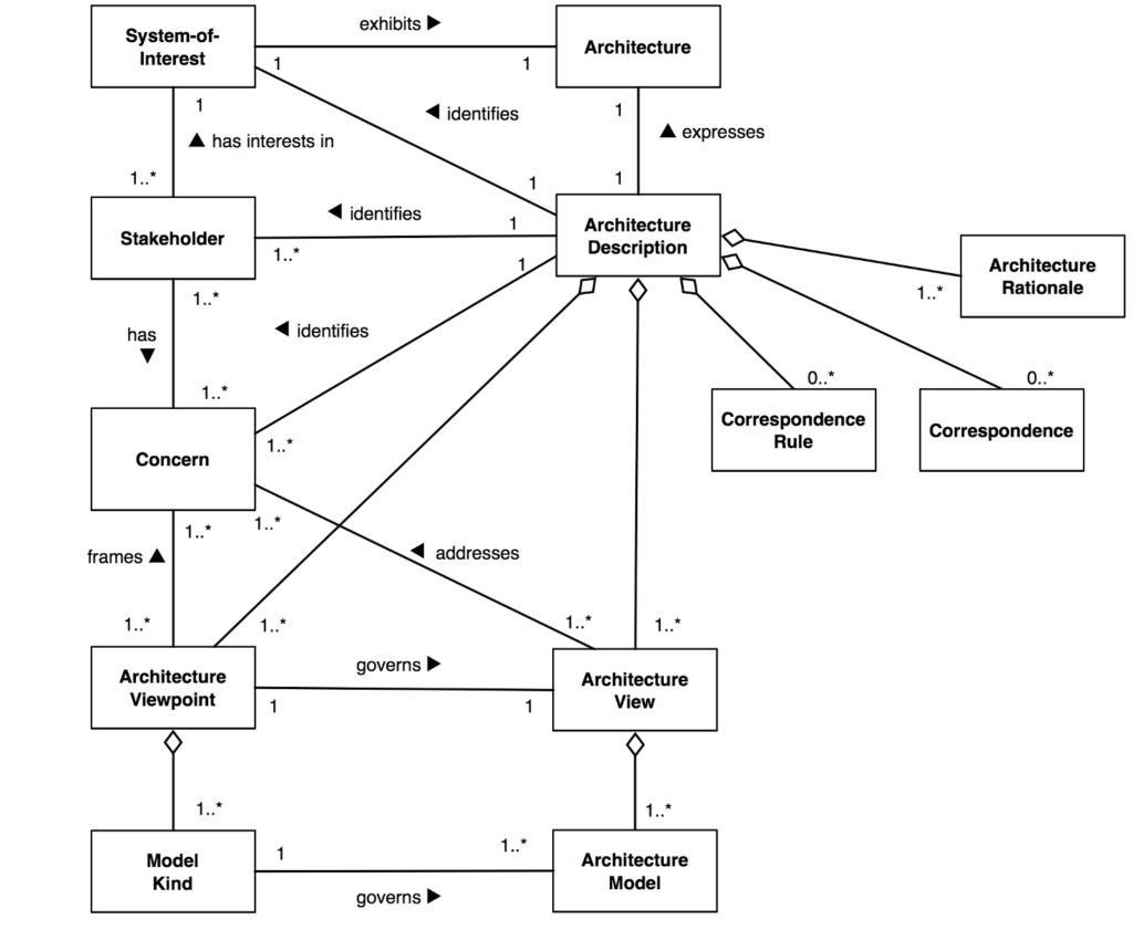
The following figure shows a relevant excerpt of the IEEE 1471 metamodel.
Figure 1 IEE 1471 Architecture Metamodel (retrieved from http://www.iso-architecture.org/viewpoints/)
The standard defines View as “a representation of a whole system from the perspective of a related set of concerns”. This representation conforms to a Viewpoint, i.e., “a specification of the conventions for constructing and using a view. A pattern or template from which to develop individual views by establishing the purposes and audience [i.e., stakeholders] for a view and the techniques for its creation and analysis.”
When addressing physical systems, a figurative analogy is also often used to better communicate and help to internalize the concepts of View and Viewpoint. For example, a common analogy is to represent the system as an object that can be observed by a human, as shown in the figure below [4]. In this analogy, a Viewpoint can be defined as the perspective from which the object is observed. Differently, the View can be imagined what is perceived.
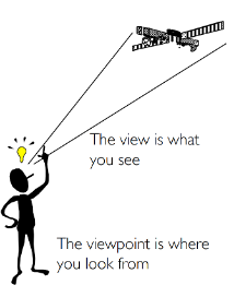
Figure 2 Visual Metaphor [4]
Enterprise Architecture Frameworks
The definition and maintenance of enterprise architecture models can be a complex task for the inherent complexity in terms of enterprise scope, number of socio-technical concepts, and number and variety of stakeholders. EA frameworks have therefore been introduced to provide guidelines and contextual system modeling schemas to support the creation and maintenance of EA models (e.g. UPDM [5], NAF [6], DoDAF [7], ESA-AF [8]). Although EA frameworks share common purposes and the above introduced concepts, these frameworks have often been tailored to the specific characteristics of the enterprise domains to further facilitating framework users to represents architectures of their interest. Several frameworks have been introduced, each addressing a specific domain and community. For example, EA framework TOGAF is of general purpose and can be applied to many business contexts [9]. Differently, the ESA-AF is for European Space-based SoS [8], while DoDAF and NAF primarily concern the military domain. DoDAF and NAF became popular and their wide adoption has motivated the definition of UPDM, a standard interoperable UML-based profile for the exchange of DoDAF and NAF models in XMI coding format. With the objective of reusing and integrating with available standards, UPDM also encapsulates UML/SySML specifications [10] along with the SOAML profile [11]. In addition, UPDM is organized into logical units, avoiding circular dependencies and offering several levels of compliances. Currently, UPDM offers two levels of compliance, Level 0 and Level 1.
UPDM Level 0 consists of three sub-profiles: Core, DoDAF and MODAF. Core profile contains the definition of elements shared by DoDAF and MODAF. Differently, DoDAF and MODAF profiles contain the definition of the respective non-shared elements. In this paper, we are interested mainly in the generic characteristics of UPDM/MODAF, and therefore we omit the description of UPDM Level 1 and of DoDAF specific aspects. The Core consists in turn of a set of architectural Viewpoints, each implemented as an UML profile. Specifically, such profiles are: All―for descriptive/metadata views on the EA model; Acquisition―for views on related to the acquisition of existing and procured systems; External types―for elements surrounding the architecture; Operational (OV)―for views on the functional architecture; Service (SV)―for views on service definition and consumption; Strategic―for views on high level capabilities, enterprise goal and mission; System―for views on the physical architecture; Technical―for views on standard and technologies used in the enterprise architecture. For each of these Viewpoints, UPDM also defines a set of Views. For example, Operational Viewpoint defines: High Level Operational Concept Graphic View (OV-1), Operational Node Relationships Description View (OV-2) and Operational Activity Model (OV-5). OV-1 provides an overall view of the scenario in which the enterprise operates. The scenario is mainly identified by the graphical or model description of the involved roles or actors. The interactions among the actors are detailed in OV-2, which formally defines the interaction directions and the interaction content. The content can be of several types: Information Element—to indicate message exchange; Resource Artifact—to indicate physical object exchange; Movement of People—to indicate the exchange of humans; and Capability Configuration—to indicate the combined exchange of Resource Artifact and Movement of People.
The Viewband Concept
The View and Viewpoint concepts cannot be used to distinguish the interleaving roles of architectural elements and interactions that characterize enterprise operation, maintenance and governance chains of enterprises in SoS configurations. This limitation can be overcome with the introduction of the Viewband concept, an abstraction primitive that can be used to support the distinction of elements and interactions roles. In line with the above description of View and Viewpoint concepts through the above visual metaphor, we exploit the visual analogy noting that:
- An actor’s eye can distinguish the color of an object
- The color is often composed by a mixture of primitive colors
- An actor can filter colors using special devices, such as sun or orange glasses or an intense external light of a complementary color.
Underlying these observations, there is the fact that the human eye and our brain can distinguish colors, basing on the perceived wave length that is refracted by objects (1). Using a prism, the white light can be separated in beams of different colors, which combination can produce any other color (2). In addition, using sunglasses or other glasses filtering the electromagnetic waves, we can alter our perception of the colors (3)―sometimes to stress the differences among objects or to minimize the visual impact of objects of given colors.
Similarly, an enterprise model is an object that is characterized by a set of related blocks, each representing an enterprise element participating in one or more life-cycle processes, i.e., operation, governance or maintenance. Aside from the structure in View and Viewpoints, the blocks need to be “colored” according to their roles in the enterprise life-cycle. This is particularly important to describe and identify interconnections among life-cycle processes in SoS configurations, contributing to highlight the critical operation-maintenance-governance chains sustaining the provisioning of new services. The Viewband concept can therefore be defined as:
“a distinguishing characteristic that can be used to indicate, and subsequently identify, the enterprise life-cycle in which an architectural element is participating”.
Applying this definition, enterprise modelers will be able to distinguish the role of a model block by “coloring” the block according to their role in an enterprise life-cycle. As a result, the blocks can be filtered to visualize only those supporting each life-cycle process. In addition, this coloring will enable enterprise architects to visually identify blocks which will be needed in the various life-cycle processes of operation, maintenance, and governance, in particular those blocks that are part of independent enterprises. This distinction is also an important point for the definition of mathematical models for SoS performance models, as failures in the maintenance or governance chains might indirectly affect the operation performance.
The Viewband concept adds additional information to the enterprise model blocks, and a non-intrusive implementation is essential to promote the application of this concept within the standard technologies of existing EA frameworks, specifically the UPDM one.
Concept Implementation
The Viewband concept introduces information concerning the enterprise operation type in which an architectural building block is participating. Using existing EA frameworks, this extra piece of information can be represented in several ways, from architectural block packaging to coloring, both physically (i.e., using a distinguished color palette), and semantically (i.e., introducing attributes). In any case, it is essential the impact that the concept implementation may produce on the conformance to the EA framework with respect to underlying standard. A possible and compliant implementation is based on the combined use of UML packages, block physical coloring and block attribute marking as extensively detailed in [2]
Example Application
Let us consider a simplified national postal enterprise for the delivery of envelops over the national territory and let us restrict our presentation to the UPDM views High Level Operational Description (OV-1), Operational Node Relationship Description (OV-2), and Operational Activity Model (OV-5).
The following figure shows the OV-1 view of the overall scenario, defining the enterprise operation as consisting of two customers, two local branches, and a national hub for the regional mail dispatching.
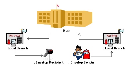
Figure 3 High Level Operational Scenario (OV-1) for a National Postal Enterprise
In the operation scenario, we assume that customers must visit the local post office for posting a mail. In addition, post vans are used to deliver mails between the hub and any of the local branches. Finally, riding a scooter, a postman delivers mails to the local customers. Aside from the operation process, we identify a simplified set of maintenance and governance processes. Concerning the enterprise maintenance, we assume that the vans and the scooters need occasional servicing for mechanical repairs and for refueling. We also limit the representation of the enterprise governance to the payments for the servicing and refueling.
Using the Viewband concept, we can model the enterprise distinguishing among operation, maintenance and governance. Using the above package method, the Viewband concept can be implemented by structuring the model packages as shown in the following figure:
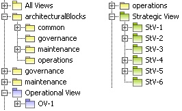
Figure 4 Package Structure
Before proceeding with the presentation of the OV-2 diagrams, the exchanged data and objects need to be identified. From the above scenario description, we have identified the entities: “Envelops”, “Envelop”, “PostVan”, “PostScooter”, “Invoice”, and “Money”. “Envelops” is a “Resource Artifact” grouping two or more “Envelop” entities, both “Resource Artifacts”. “PostVan” is a “Capability Configuration” consisting of a “Driver” and a “Van”. “PostScooter” consists of a “Postman” driving a “Scooter”. “Invoice” and “Money” are “Resource Artifacts”.
The following figures show the OV-2 and OV-5 diagrams representing the enterprise operation, maintenance, and governance in our simplified scenario.
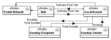
Figure 5 Operation OV-2 View

Figure 6 Operation OV-5 for Local Branch
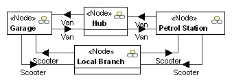
Figure 7 Maintenance OV-2

Figure 8 Maintenance OV-5 for Local Branch and Hub

Figure 9 Governance OV-2
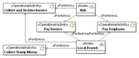
Figure 10 Governance OV-5 for Local Branch and Hub
With the objective of supporting an engineering process from a system thinking perspective, we use the physical coloring method to derive a combined OV-2 diagram illustrating the interleaving of the enterprise operation, maintenance and governance interactions. The resulting OV-2 is shown in the figure below, where red indicates the operation, blue indicates the maintenance and green indicates the governance.
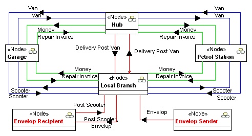
Figure 11 Combined Operation-Maintenance-Governance OV-2
With the Viewband concept and the above exemplified approach, it is possible to highlight and make machine interpretable the maintenance and governance interactions that sustain the enterprise operations of mail collection, dispatching and delivery. In addition, browsing the enterprise model from this diagram, more punctual information can be inferred, concerning the enterprises integrations across these life-cycle processes.
References
- Jamshidi, M., Systems of Systems Engineering: Innovation for the 21st Century. John Wiley & Sons, 2019.
- Gianni, D. and D’Ambrogio, A., “The Viewband concept: Introducing life-cycle modeling in enterprise architectural frameworks,” 7th International Conference on System of Systems Engineering (SoSE), Genova, Italy, 2012, pp. 71-76
- IEEE Std 1471 Recommended Practice for Architectural Description of Software-Intensive Systems. IEEE (2011).
- Hilliard, R.: All About IEEE Std 1471. (2007).
- OMG, UPDM Specification v 2.1.1., https://www.omg.org/spec/UPDM (last access February 2024).
- NAF: NATO Architecture Framework – detailed guidance, https://www.nato.int/cps/en/natohq/topics_157575.htm (last access February 2024).
- US DoD, DoDAF, https://dodcio.defense.gov/library/dod-architecture-framework/ (last access February 2024).
- Gianni, D., Lindman, N., Fuchs, J., Suzic, R., “Introducing the European Space Agency Architectural Framework for Space-based Systems of Systems Engineering,” In: Hammami, O., Krob, D., Voirin, J.-L. (eds.): Proceedings of the 2nd International Conference on Complex Systems Design & Management (CSDM 2011). Springer Verlag, Paris (2011) pp 335-346.
- The Open Group, TOGAF – The Open Group Architecture Framework – v 9.2, (2011).
- Friedenthal, S., Moore, A., Steiner, R.: A Practical Guide to SysML: The Systems Modeling Language. Morgan Kaufmann (2008).
- OMG, SOAML Specification v 1.0.1, https://www.omg.org/spec/SoaML/ (last access February 2024).

